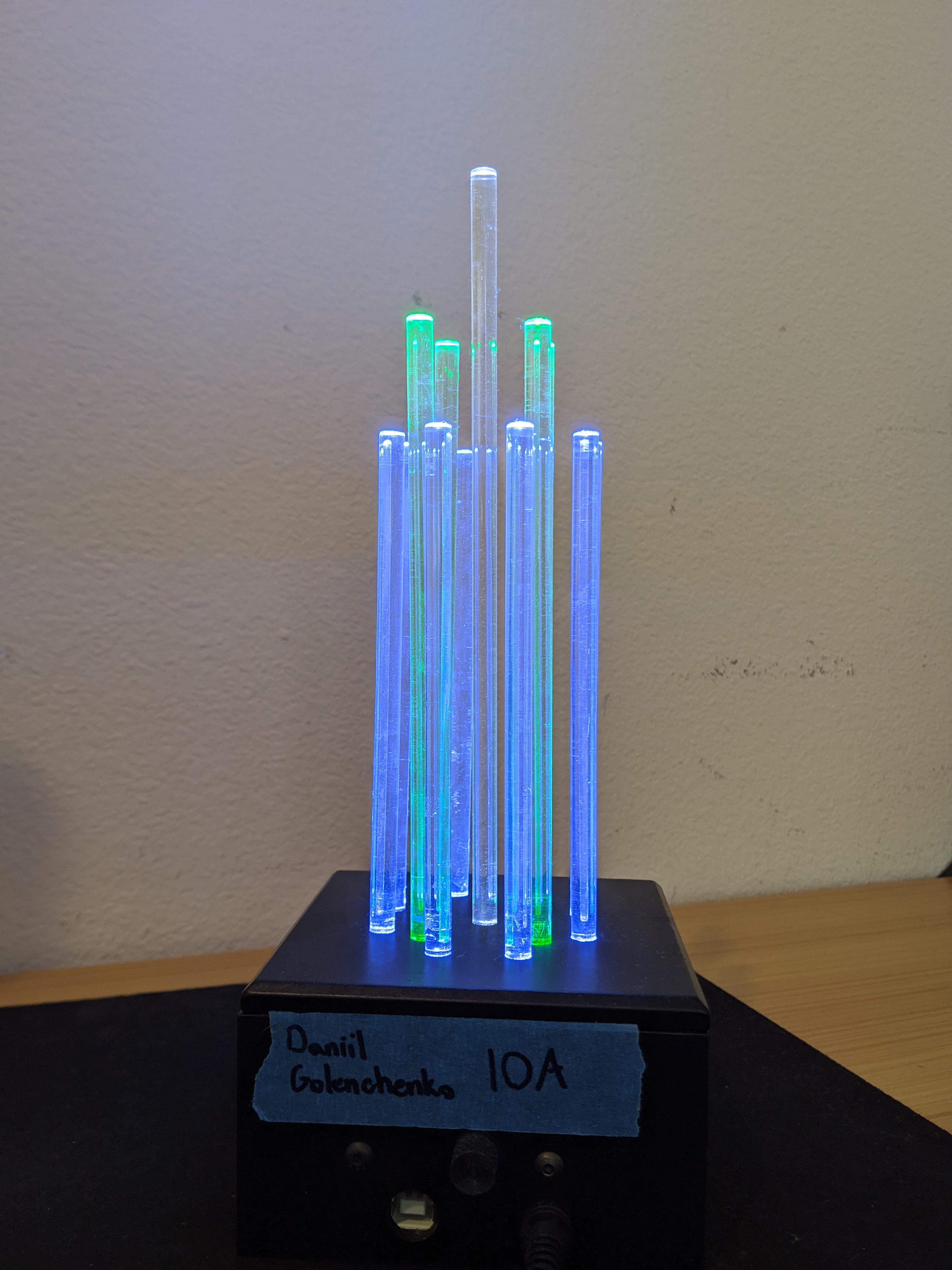
My Light Sculpture (Figure 1) was created around the analogous color scheme of blue and green, with white substituting a third variation of either blue or green. The pattern of the light rods was created to be symmetric and to ascend in height as the rods got closer to the center for a pleasing aesthetic. The blue rods resemble ocean water and the green rods resemble seawater, but no particular theme is present.
During the Art rotation we learned about concentric planes (polar coordinates) in order to properly position our rods and incorporate rotational symmetry. A lot of time was spent on creating aesthetically pleasing patterns and calculating their coordinates to later use during the 3D modelling process.
The rotation was primarly used to solder the circuit board (Figure 2) and Arduino at the core of our sculpture. I learned how to solder wires and LEDs, as well as how to shrink wrap wire. Not only did I learn how to solder, but how do it properly. I practices until I was able to avoid cold joints (not enough heating through the solder) and an overruse of solder.


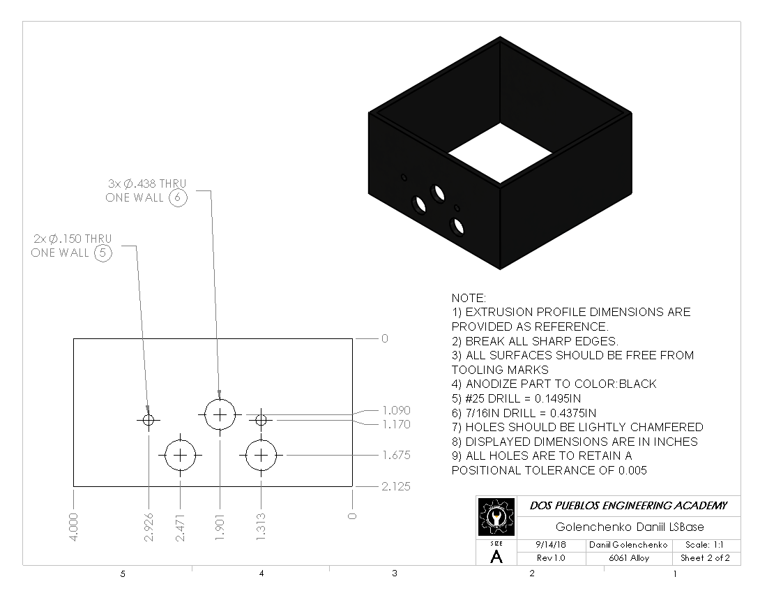
In the machine shop I manufactured most of the sculpture. I created a base (Figure 3), a knob, and the clear rods.
In specific I used the mill to cut my base to size and drill holes for the knob and plugs. For the knob I learned how to use facing tools in order to create a diamond grip. Finally, I used the lathe to cut clear acryllic rods to length and polished them with different types of polish, making sure to get rid of any possible scratches or blurriness in the rods. The process proved to be rigorous and timely, as the slighest scratch could effect the brightness of the rod and light's spread through the rod.


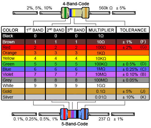
In the physics rotation I learned about circuits and their components, such as resistors, LEDs, and capacitors. Using Ohm's law I calculated the necessary resistors for my specific LED colors, as certain colors required a different resistor. I also learned how resistors are labeled, utilizing the Resistor Color Code (Figure 4). I also learned how to crate circuit diagrams and used them to work with breadboards.
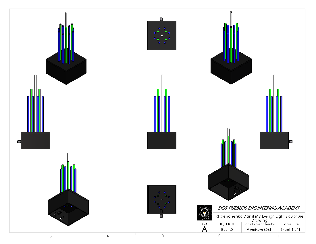
The time spent in CAD was primarly used to create a 3D model (Figure 5) of the full light sculpture in SolidWorks, as well as create blueprints for the necessary components. Being able to visualize the sculpture on a computer screen helped me easily adjust the rod lengths and patterns to find the optimal and best looking variation.
Another aspect of CAD was programming using the Arduino for the first time. We learned the necessary function of C++ in order to create a program than when run on the Arduino, would make the LEDs light up in the correct order and with the proper timing. Using for loops and incrementing I was able to write efficient code that essentially automated the pattern creation process.